Hardware Documentation and Howto's: Difference between revisions
From pCT
| Line 9: | Line 9: | ||
* [[:Media:PRU Address Map.pdf | pRU Address Map]] | * [[:Media:PRU Address Map.pdf | pRU Address Map]] | ||
* [[:Media:PRU Ethernet Configurations.pdf | pRU Ethernet Configurations]] | * [[:Media:PRU Ethernet Configurations.pdf | pRU Ethernet Configurations]] | ||
=== pRU Bus System === | |||
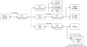
[[File:Bus tree.png|thumb|left]] | |||
The pRU bus system is connecting the various modules on the FPGA to a common master, the Microblaze Subsystem. | |||
Each of the modules is associated with a given BASE-ADDRESS specified in the [[:Media:Control Interface.pdf | pRU Control Interface Document]]. | |||
Note that several instances do exist for certain modules. E.g. there are one alpide_data instance for each ALPIDE chip connected to the pRU. | |||
To communicate with a specific instance one needs to add an offset of 0x1000 times the instance number to the module base address. | |||
E.g. if you want to communicate with instance 16 of the alpide_data module: | |||
<ALPIDE_DATA_BASEADDR> + (0x1000 * 16) | |||
Revision as of 16:30, 12 September 2019
Getting Started
Documentation
pRU Bus System

The pRU bus system is connecting the various modules on the FPGA to a common master, the Microblaze Subsystem. Each of the modules is associated with a given BASE-ADDRESS specified in the pRU Control Interface Document. Note that several instances do exist for certain modules. E.g. there are one alpide_data instance for each ALPIDE chip connected to the pRU. To communicate with a specific instance one needs to add an offset of 0x1000 times the instance number to the module base address.
E.g. if you want to communicate with instance 16 of the alpide_data module:
<ALPIDE_DATA_BASEADDR> + (0x1000 * 16)
