Hardware Documentation and Howto's: Difference between revisions
From pCT
mNo edit summary |
mNo edit summary |
||
| Line 43: | Line 43: | ||
* [[:Media:Ptb_regs.pdf | ptb_regs]] | * [[:Media:Ptb_regs.pdf | ptb_regs]] | ||
=== Transition Card === | === Transition Card (TC) === | ||
* [[:Media:TC-v1.0_schematic.pdf | TC-v1.0 Schematic]] | |||
=== ALPIDE Chip === | === ALPIDE Chip === | ||
Revision as of 10:36, 12 January 2020
Getting Started
Documentation
pRU
- pRU Control Interface
- pRU Address Map
- pRU Ethernet Configurations
- pCT Data Transfer Protocol
- pRU Data Format
pRU Registers and Bus System
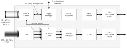
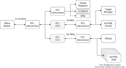
The pRU bus system is connecting the various modules on the FPGA to a common master, the Microblaze Subsystem. Each of the modules is associated with a given BASE-ADDRESS specified in the pRU Control Interface Document. Note that several instances do exist for certain modules. E.g. there are one alpide_data instance for each ALPIDE chip connected to the pRU. To communicate with a specific instance one needs to add an offset of 0x1000 times the instance number to the module base address.
E.g. if you want to communicate with the
- 1st instance: <ALPIDE_DATA_BASEADDR>
- 2nd instance: <ALPIDE_DATA_BASEADDR> + (0x1000 * (2-1))
- 16th instance: <ALPIDE_DATA_BASEADDR> + (0x1000 * (16-1))


